Ever since I started watching ThePrimeagen and his Kinesis keyboard, I have wanted to try one out for a very long time. Initially, I couldn't justify spending so much money, so I decided to take matters into my own hands. Thus, a new project was born.
Bill of Materials (BOM)
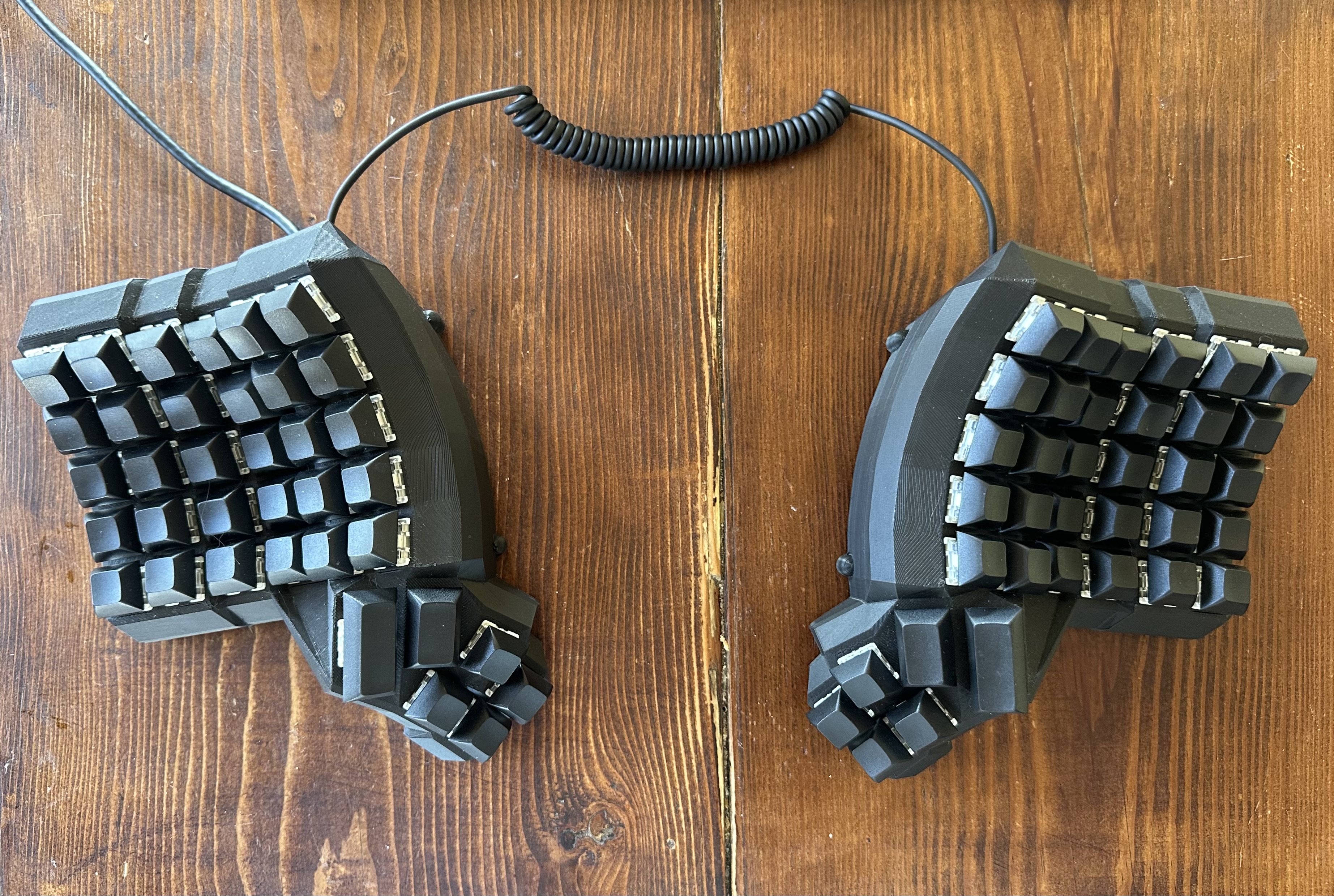
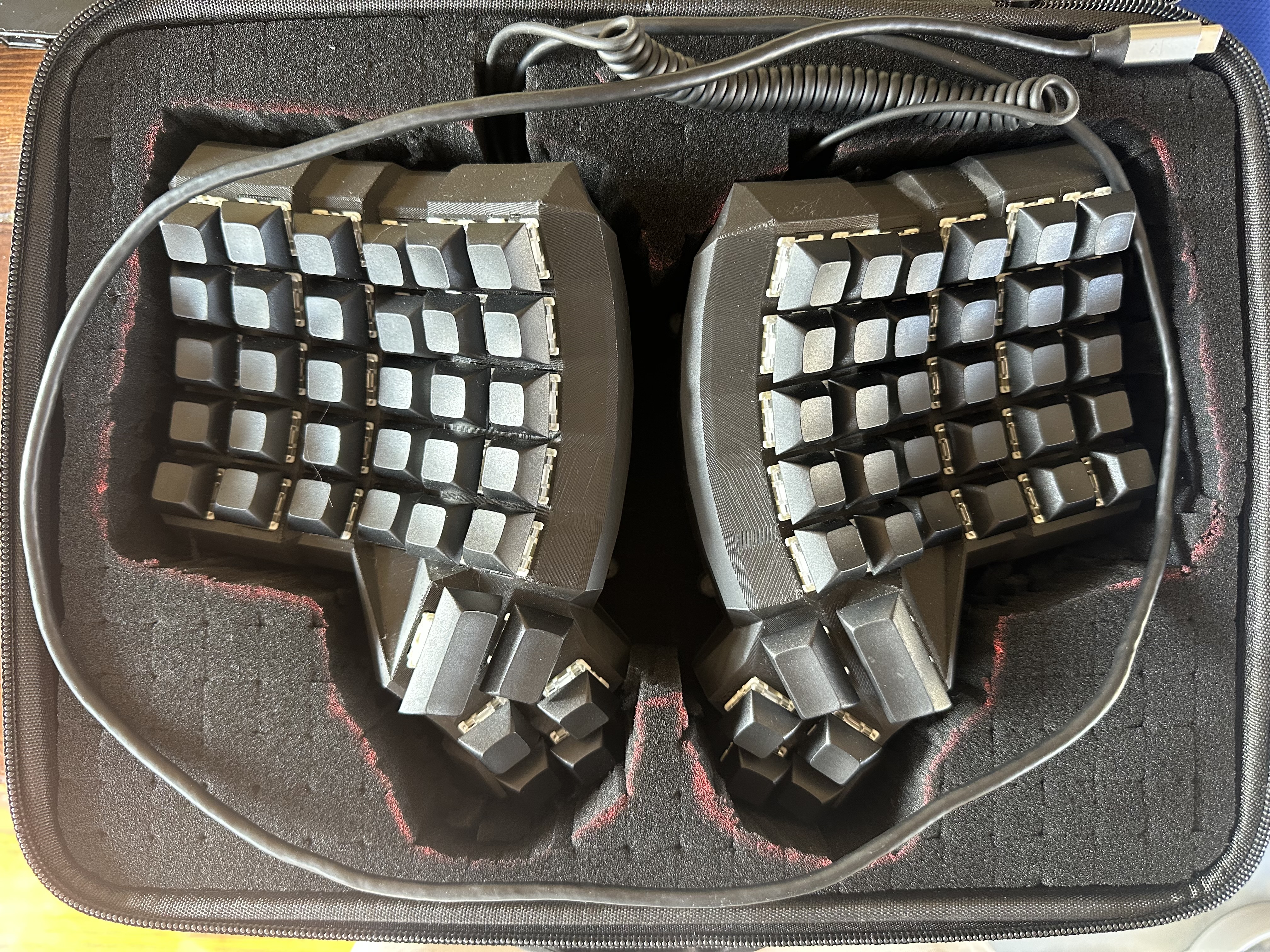
I chose a Dactyl Manuform layout, but these materials are standard for DIY keyboards:
- 2 Pro Micro Boards
- Diodes (1N4148)
- Key Switches and Caps
- TRRS Cable and Jacks
- Solid Core Wire
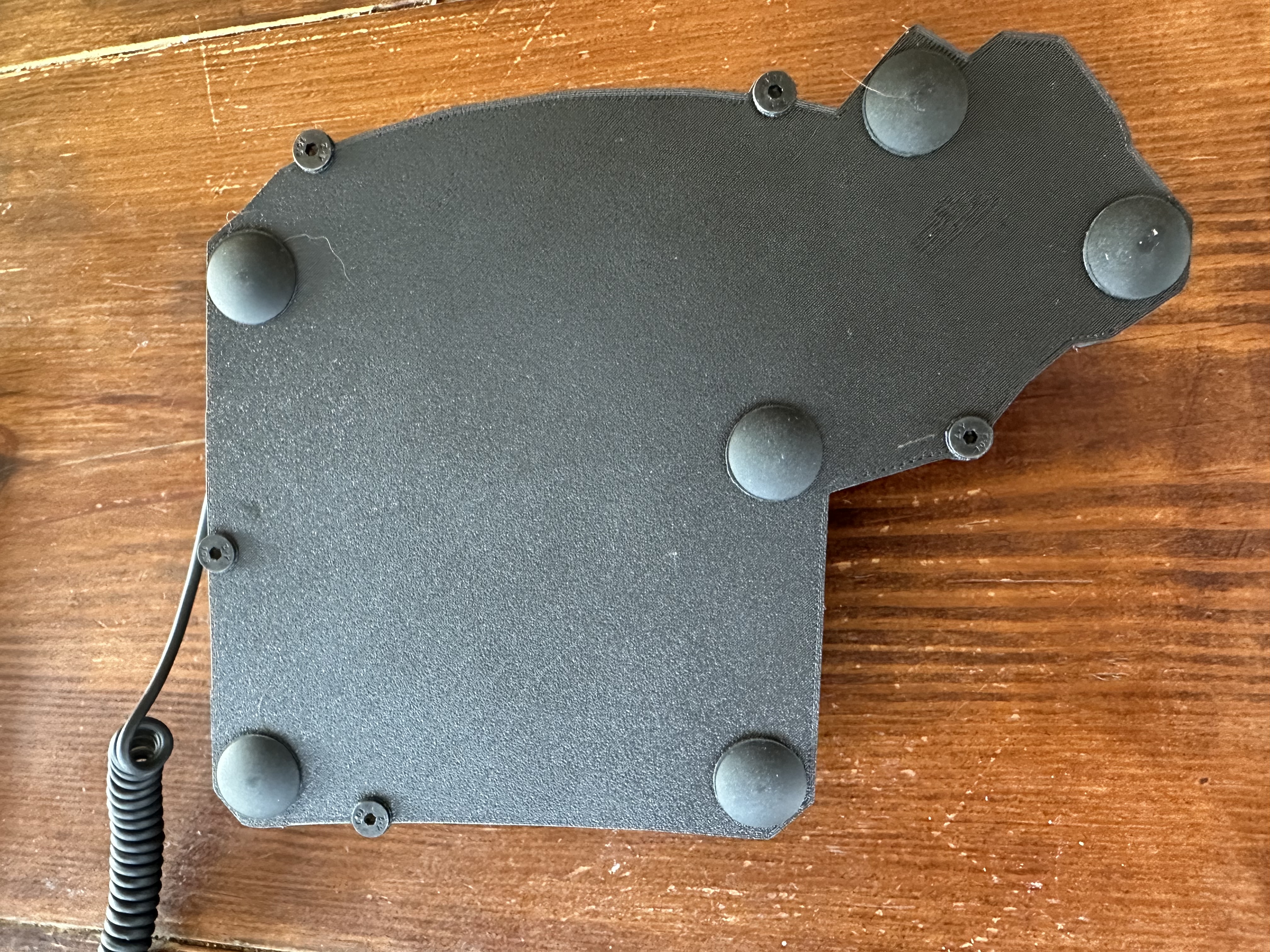
- M4 Heat Inserts and Screws
- 3D Printed Case
I also used a soldering iron, lead-free solder, wire strippers, and a multimeter for testing solder points.
Project Goals
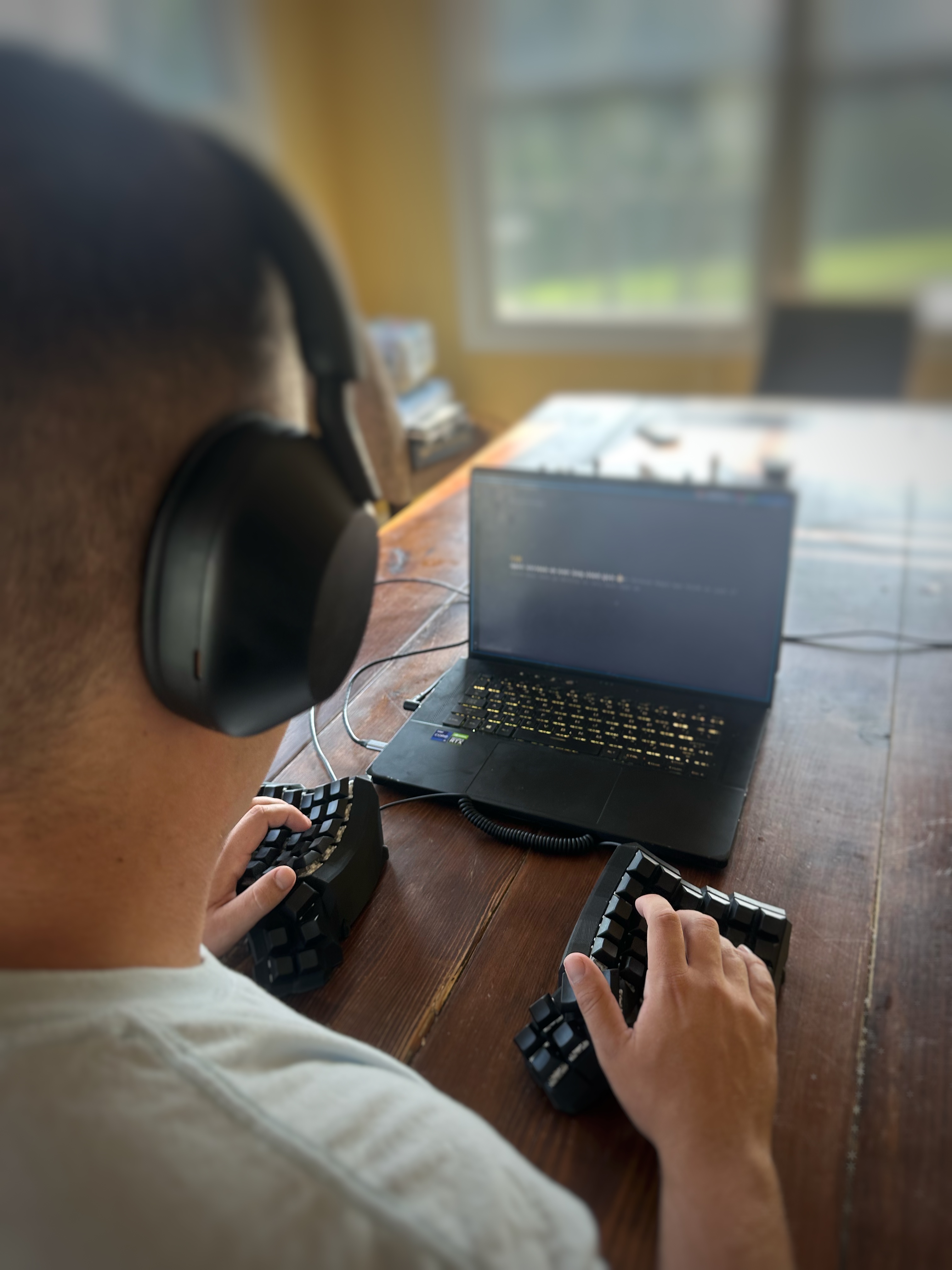
My main goals were simple: learn about keyboard design, implement USB-C, have fun, and complete the project efficiently. Functionality, durability, and good ergonomics were non-negotiable.
Keyboard Matrix & Ghosting Prevention
A keyboard is basically a grid of wires (rows × columns), a bunch of switches sitting at the intersections, and a tiny brain (microcontroller) that scans that grid super fast to figure out which switch closed. No magic, just clever wiring and some firmware doing laps. This matrix adaptation of a keyboard is what allows smaller hardware to make quick scans for key presses. Instead of one pin per key, keys share wires in a matrix. Each switch connects a row to a column. Press a key > that row and column are now electrically connected. What happens is...
- The microcontroller sets one row "active" at a time (drives it high/low).
- It then reads all the columns to see which ones are "lit up".
- It moves to the next row and repeats. This happens thousands of times per second.
From that row+column pair, it knows exactly which key you hit. Fast enough that it feels instant. You may be asking about multiple keys being pressed at once right about now. Let's take, for example, a 2x2 keyboard. If I were to hold down the keys in position (1,1), (1,2) and (2,1), the microcontroller will notice that rows 1 and 2 are active, and columns 1 and 2 are also active. Therefore, the key in position (2,2) would appeae as pressed, and is therefore "ghosted". Without diodes, current can sneak through multiple pressed switches and make it look like an extra key (the "fourth corner" of a rectangle) is pressed. A diode on each switch forces current to flow in only one direction, so signals don't backfeed through other keys, which fixes the ghosting problem! To deal with all of these columns and rows, we will deploy a firmware (QMK in my case) to the microcontroller to deal with taking the data from current to serial data. It does this with the following features and techniques:
- Matrix scanning: Runs that row>column loop nonstop to detect closures.
- Debouncing: Mechanical switches "chatter" for a few ms; firmware smooths that into a single press.
- Keymap & layers: Maps row/col positions to actual keycodes, plus your layers/macros.
- Split comms (for two halves): One side is master. It scans its half, receives the other half's scan data over TRRS/serial, merges both, then sends a single USB HID report to the computer.
So the flow ends up looking loke this: Switch press > row/column connect > diode keeps it one-way > MCU sees it during scan > firmware debounces & maps > USB HID event > OS gets a keypress
Build Process
The build process followed these main steps:
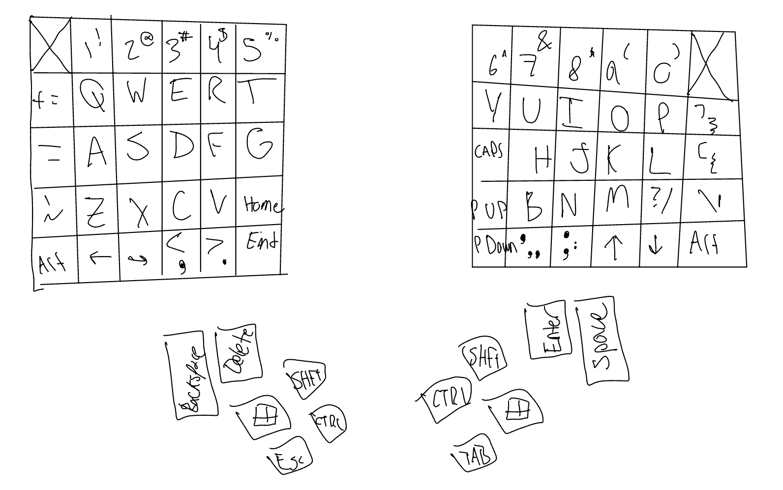
- Planning the layout: Decided on a 5-row, 6-column layout with a 6-key thumb cluster and mapped out the key positions.
- Handwiring the keyboard matrix: Wired all switches to rows and columns, adding diodes to prevent ghosting and ensure accurate key detection.
- Connecting the microcontrollers: Soldered the Pro Micro boards and connected them using a TRRS cable for split keyboard communication.
- Case assembly: Placed all components into the 3D printed case and secured with M4 heat inserts and screws.
- Key installation: Inserted the switches and keycaps, double-checking each row and column for proper connectivity.
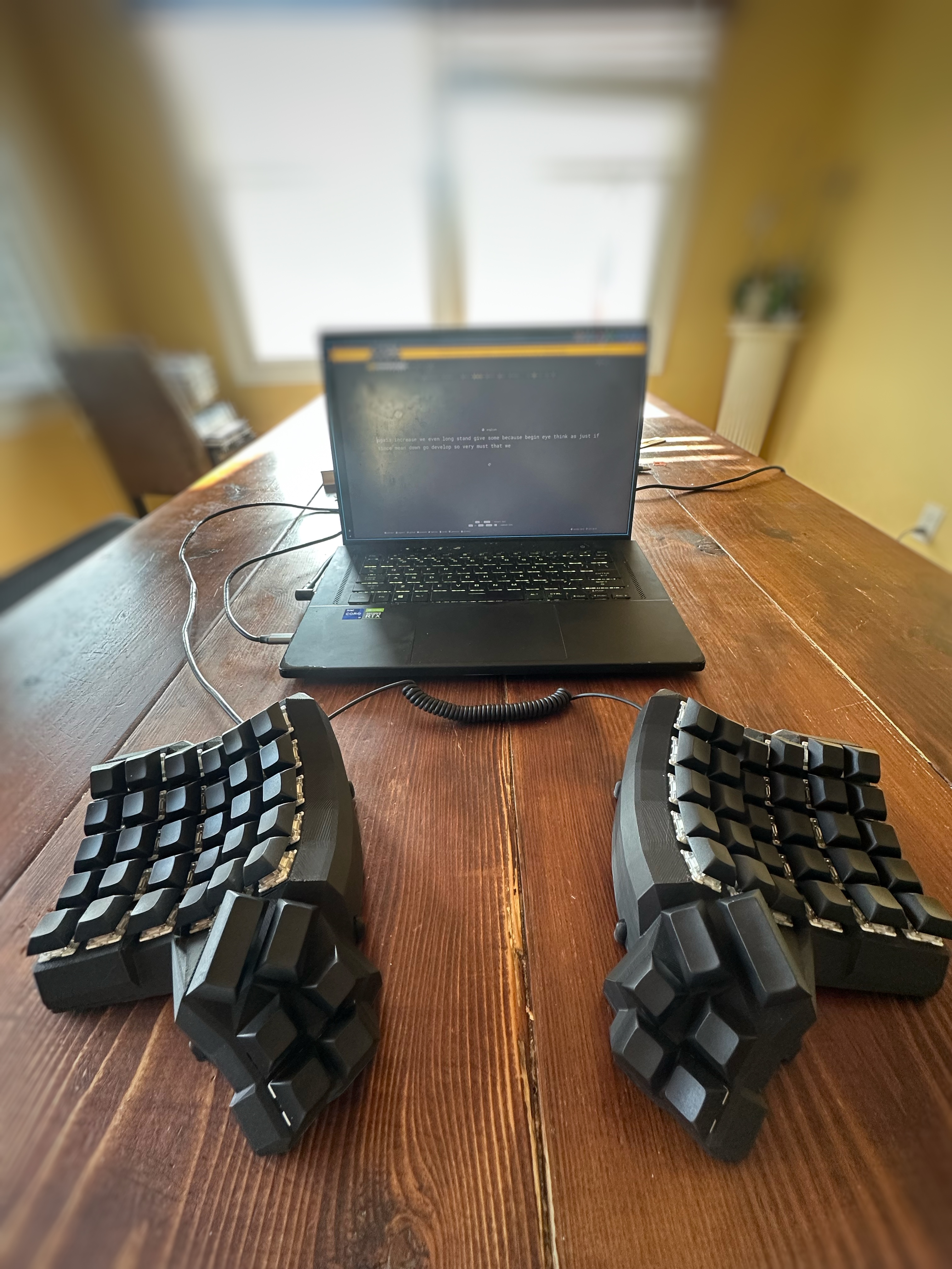
- Firmware & Testing: Uploaded the QMK firmware, tested each key, and ensured ghosting was prevented and everything worked correctly.